SEMA News - May 2009
RESEARCH
By Oscar Muñoz
Computer Tools for Design
Making the Most of Technology
 | |
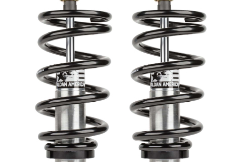
CAD systems allow your company to make designs such as this and enable you to take advantage of technologies geared toward bringing your product to market faster, better and at a lower cost. |
The primary benefit of using CAD is the streamlining it creates for the development of new products, which can be coupled to third-party software tools that extend functionality beyond the basics of mechanical design. Reverse engineering, rapid prototyping and computer-aided manufacturing (CAM) are just a few examples of tools that work within CAD applications to maximize development for any manufacturing organization. We’d like to offer a glimpse at the technologies that are available and can be easily integrated with your CAD software to reduce your research and development and enhance some of your consumer-outreach operations.
MCAD Application
Mechanical computer-aided design/drafting (MCAD) software provides engineers with an array of features that allows them to more easily develop products. At the core of each application is a modeling feature that lets the user create sketches from which a 3-D component will be produced. Generally speaking, most designs begin from a 2-D sketch and progress from there into a final design once depth and details are worked in. The process can be time-consuming, particularly if the model carries high levels of detail. However, the software provides a rich set of tools and wizards that make the process progress smoothly. Fillets, cuts, extrusions, edges, drafts, shells, patterns and ribs are all preset functions available through a button or wizard that simplifies the process. If you’re not sure, a simple click on a pull-down menu will get you started on a tutorial for further guidance.
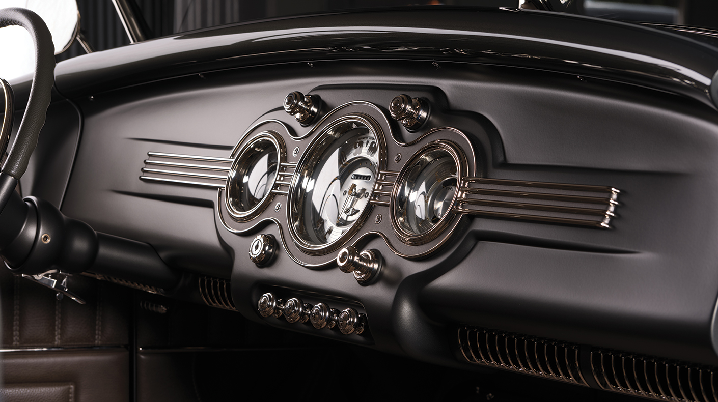
 | CAD software helps your company with more than design and manufacturing. In a matter of minutes you can take a CAD drawing (p. 44) and create a photorealistic rendering (above) to increase the appeal of proposals, marketing brochures or presentations—extending its reach into more aspects of your business operations than just R&D. |
As you move from part design to assembly modeling, you begin to position and define the relationships between the parts of the assembly. Parts that have a set of motion relations with respect to each component (i.e. sprockets, pulleys, linkages) would be linked with each other so that clicking and dragging any part of the moving set would simulate the corresponding motion among involved parts. This helps identify interference with nearby parts or possible collisions as well as observe and measure relative velocities and accelerations that can be used to further analyze the forces in the system and better engineer the product. Other features of note are bill-of-materials generation and photorealistic rendering. Both not only facilitate communications between the engineer and other departments in the organization, but also provide content that can be used in the development of proposals, presentations and virtual demonstrations of the product, which help reduce the additional costs of having other departments create the material from scratch.
If you’re interested in evaluating a CAD software package, several companies offer free trial versions, including AutoCAD, Rhino3D and SolidWorks.
| |
A rapid prototyping machine can take your CAD design and provide you with a prototype within one to two days. SEMA uses this model from Dimension Printing to provide rapid prototyping service to its members. |

Reverse Engineering
Reverse engineering tools are aids to designing products that will be installed on a vehicle. In order for the parts to fit and function as designed, accurate measurements need to be taken. A two-part combination of tools is needed to easily and effectively capture this data and import it into your CAD software. A 3-D measurement tool is used to capture the data from either a part that has been fabricated without CAD or an existing part taken from a vehicle. There are two main types of tools: a contact type, where the machine needs to physically touch the target object being digitized, and a non-contact type, such as a laser scanner or camera that projects light on the target object and captures the reflected light. In either case, the machine establishes a reference frame and sends point coordinates to a connected laptop. Captured data can then be fed to the second part of the tool combination, a specialized software application that will place the dots into a virtual 3-D space and reconstruct the object, identifying key features and constructing them as you would in your CAD software. The result is a precise CAD representation of the object you scanned, ready to use in a fraction of the time it would take without these tools.
There are a number of features and parameters to look for in 3-D measuring tools:
Scan Accuracy–Range from .008-inch to .001-inch; accuracy is determined by comparing the variation between the actual point on the part versus the scanned point.
Scan Rate–Point-and-click (approximately point per second) to upward of 28,000 points per second.
Mobility–Solutions are offered for either fixed-station use or portability.
Size–The size of the components to be digitized may dictate the size of digitizer needed.
Functions to look for in scan-to-CAD software include:
Feature Recognition–Capability to reconstruct the part as a detailed CAD part object, allowing for manipulation through the CAD software tools.
Compatibility–Your CAD software and 3-D measuring tool need to be compatible with the scan-to-CAD software.
Rapid Prototyping
A key phase in the development process is validation of your design through testing. Doing so requires the production of prototypes to be used in evaluating the fit of the part as well as to benchmark and fine-tune the desired functional characteristics. The process is iterative, requiring multiple prototypes, with each implementing a design change or revision to further refine the design. Rapid prototyping enables you to produce prototypes directly from your CAD data, with lead times ranging from one to five days. Rapid prototyping machines build by joining layers of material into a desired shape. The costs for rapid prototypes are relatively low because there is no need to create tooling, and they provide one of the quickest approaches to building prototypes, thereby maximizing time usage.
 |
Reverse engineering—This ’32 Ford coupe is captured in 3-D using a 3-D Laser Scanner and Point Cloud software. |
Machine Type–Stereolithography, selective laser sintering, fused deposition modeling, laminated object manufacturing and 3-D printing.
Material–Material selection is dictated by the machine, which includes photopolymer, polyamide material, epoxy-type resin and ABS plastic. Some are better used in form and fit evaluations, while others are strong enough to use in functional testing.
Size Capacity–Build envelopes vary. Packaged software may allow for splitting larger parts into smaller pieces that may be built by the machine.
Layer Thickness–Ranges from .004-inch to .0013-inch.
SEMA currently offers rapid prototyping as an extension of the Technology Transfer program to help introduce the technology’s benefits to its members.
CAM
If your company uses computer numeric control (CNC) machines as part of your manufacturing process, then you may also want to take a look at CAM software options. CNC machines offer repeatable accuracy and efficiency in manufacturing. CAM software analyzes the various part features of your design, identifying machinable surfaces and detecting the best path to take and then creating the program for all types of numerical control machines, including milling, turning, mold and die, multi-axis and more.
While most SEMA members say that they are using CAD, newer tools are available that utilize the drawings and turn traditional manufacturing into a high-tech and money-saving process. These new computer tools make the most of technology.